Quick Start Guide
Required hardware
- PhotonDrive ESC-R-150
- PhotonDrive PDB 500 HotSwap or another compatible power distribution board
- Flight controller
- BLDC motor
- Battery compatible with every connected component: 15–60 V at the ESC; 6S–13S LiPo (21.0–54.6 V) when using the PDB 500 HotSwap, or 8S–13S if its 15 V output is needed
- Power leads and connectors sized for the installation’s current and cooling
- Signal wire
Battery compatibility
The ESC input must stay within 15–60 V at full charge and under load. If you use the PDB 500 HotSwap, the complete system is limited to 6S–13S LiPo (21.0–54.6 V), or 8S–13S when its 15 V output is needed. Every motor controller and auxiliary load must support the selected supply.
Power the PDB from a battery. Do not use a bench supply or current limiter that folds back or collapses the PDB input to 0 V. Follow the PDB’s first-power-up procedure.
Wiring diagram
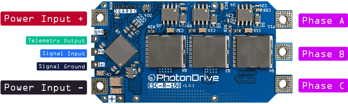
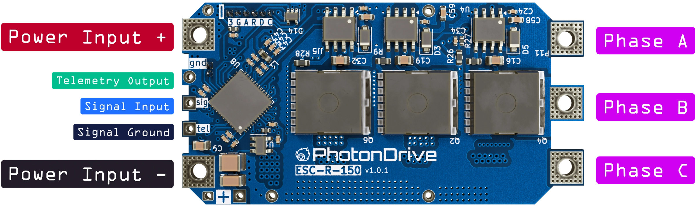
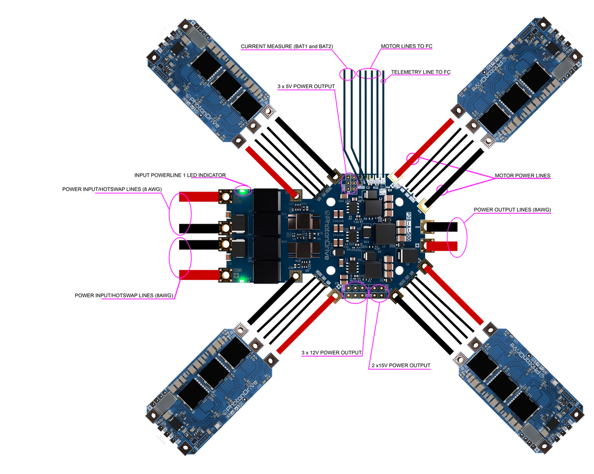
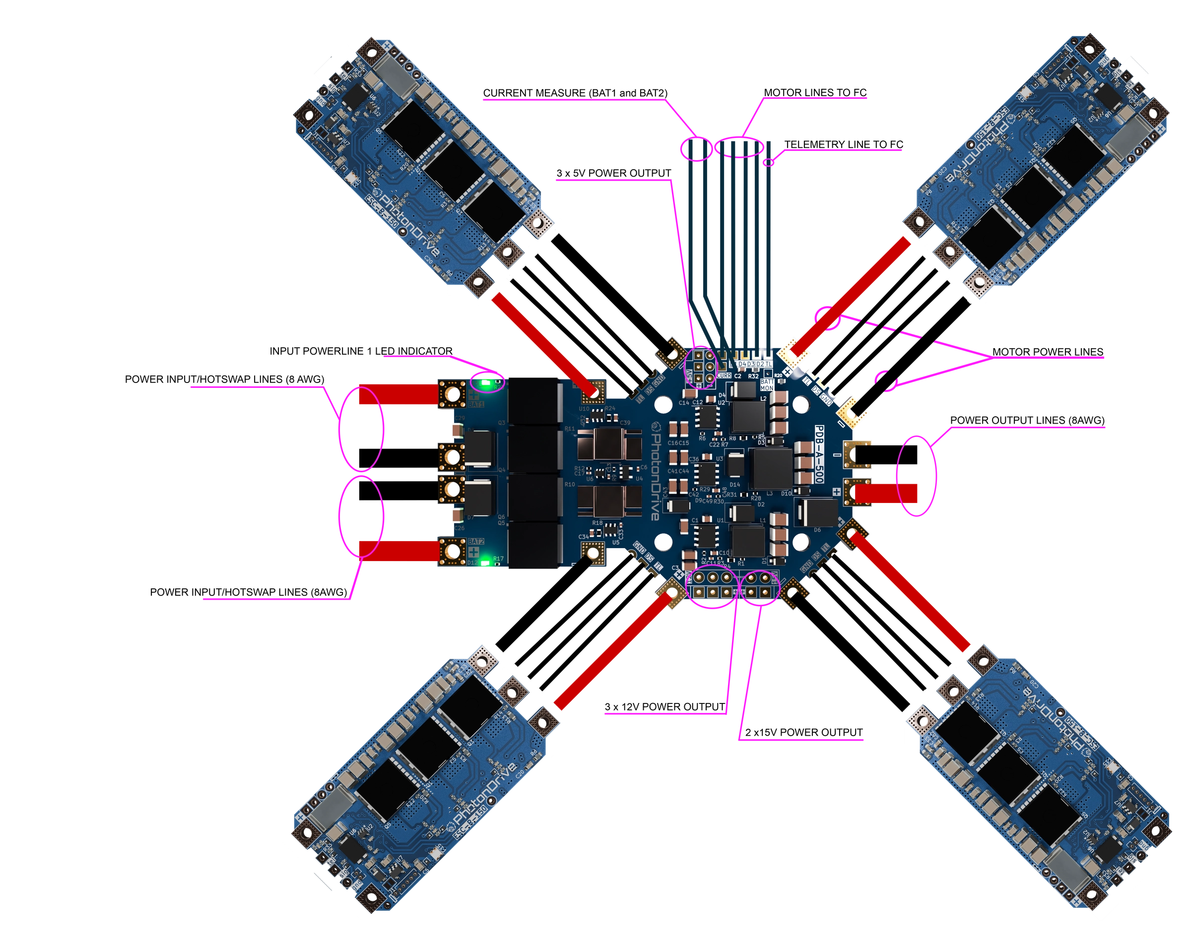
Confirm every connection against the diagrams below. The ESC-R-150 works with the PhotonDrive PDB 500 HotSwap or another power distribution board that meets the voltage and current requirements of the installation.
Soldering the power leads
The battery pads are backed by eight layers of heavy copper behind a 2.5 mm hole, so they draw heat away quickly. Given enough energy they wet cleanly; starved of it, a joint can look finished without being sound.
- Preheat the board rather than driving all the energy through the tip. A cold board needs long tip contact, and long contact is what causes damage.
- Use a chisel tip with real thermal mass, not a fine point, and keep the contact time short.
- Keep the iron on the battery pad. Components sit less than half a millimeter away — the tip must not touch them or the copper between.
- Provide strain relief. The lead is heavy and lands beside a rigid component, so vibration and any pull on the wire go into its joint.
Before first power-up, check that each joint is fully wetted and bright, that no solder has flowed toward neighboring pads, and that nothing bridges the positive pad to nearby ground copper.
Joint resistance dissipates power as the square of current, and the ESC’s temperature sensor sits with the MOSFETs rather than at the terminals. Sound terminations and adequate airflow are what make the published sustained figures achievable in your installation.
First power-up
Remove the propeller before applying power. Check polarity and measure for a short circuit between the power leads. For the first test, use the low end of the complete system’s rated voltage range — not a voltage below the minimum rating of the PDB or other connected equipment.
Connect the battery and power up the system. The ESC should initialize, and the motor should emit its startup tones.
Configuration
Each ESC can be configured through the flight controller, using a compatible Betaflight passthrough connection and the ESCape32 CLI. See the configuration reference.
With ESCape32 revision 17 or later installed and CRSF enabled, the ESC-R-150 can also be configured directly from your radio through the standard ExpressLRS Lua script. See Radio Configuration.
The links below describe the installed ESCape32 firmware. If you install another firmware build made specifically for the ESC-R-150, follow that project’s configuration instructions.
For low-level configuration, see the ESCape32 settings reference. ESCape32 also supports DShot programming while the ESC is connected to a compatible flight controller.
Flashing custom firmware
Firmware installation is intended for experienced users. An incorrect bootloader, target or connection can leave the ESC unresponsive and may damage the hardware.
The ESC-R-150 supports firmware updates over its signal line and bootloader recovery over SWD. See Firmware for official builds and the Flashing Guide for both procedures.
Need help with your setup? Contact us.