Flashing Guide
Firmware installation is intended for experienced users. An incorrect bootloader, target or connection can leave the ESC unresponsive and may damage the hardware.
The board ships with a bootloader and firmware installed. If revision 4 of BOOT4_PA2 is already installed and protected, start at Firmware flashing. Otherwise, follow Bootloader flashing first.
Disconnect power before changing any wiring. Remove the propeller and secure the motor before applying power to the ESC.
Using the Prog Tool? Follow its Quick Start Guide for the built-in SWD and serial interfaces. The procedure below uses separate adapters.
Required hardware
- PhotonDrive ESC-R-150
- USB-to-serial adapter and the circuit shown below
- Power source within the ESC’s rated input range
- Power leads and connectors appropriate for the installation
- Signal wire
- ST-Link V2 programmer only if the bootloader is missing, damaged or outdated
Required software
- ESCape32 Tools for serial firmware updates and configuration
- STM32CubeProgrammer only for bootloader recovery with an external ST-Link
The ESC-R-150 is an official ESCape32 target named PHOTONDRIVE1.
Download that firmware and its matching BOOT4_PA2 bootloader from the
Firmware page.
Match the bootloader to the target. BOOT4_PA2 is the only correct bootloader for the ESC-R-150 — its input pin is PA2.
Firmware flashing
With the ESC power disconnected, connect a USB-to-serial adapter to the input signal pin through the diode-transistor circuit:
- RX to Collector
- TX to Base through a 1 kΩ resistor
- Emitter to ESC Input Signal
- Emitter to TX via a diode
- GND to ESC GND
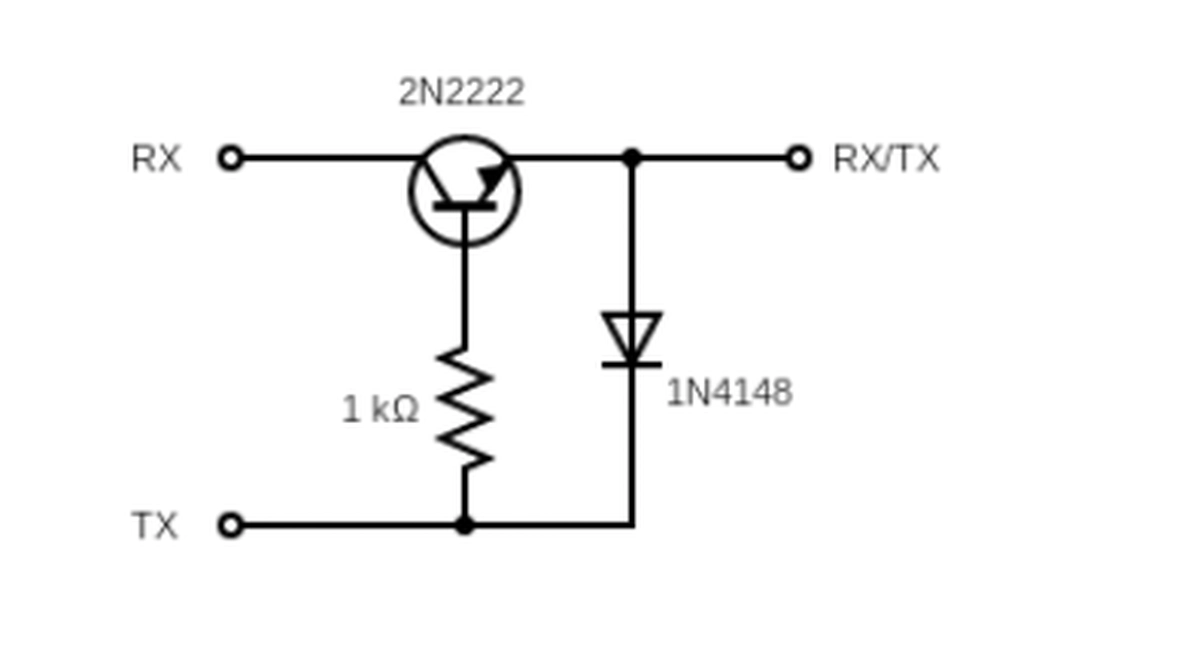
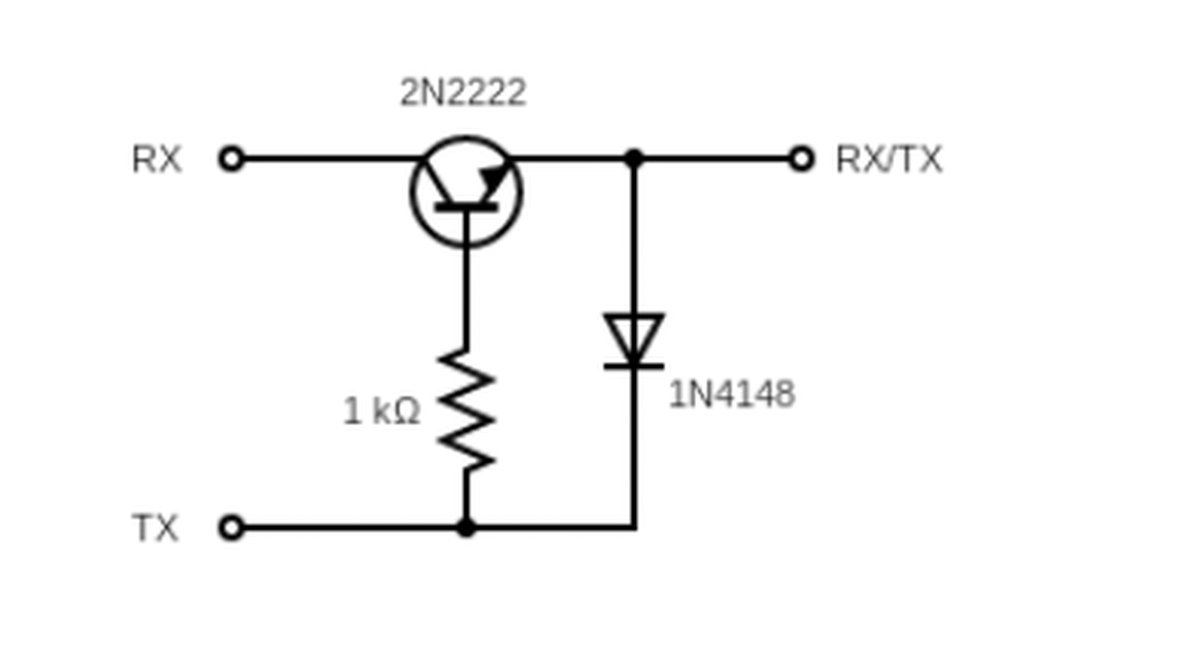
Check the wiring, keep the propeller removed, and power the ESC from a protected source within its rated input range.
Flash the
PHOTONDRIVE1firmware using the ESCape32 Tools../escape32-update -d <serial-port> <path-to-firmware-file>On Windows, use serial port format
/dev/ttyS#where#is the COM port number minus one (e.g.,COM4→/dev/ttyS3).The diode-transistor circuit provides a two-way connection, so no extra flag is required. A one-way connection — such as TX and GND only, or Betaflight passthrough — requires
-fto force the update.For more information, see the ESCape32 installation guide.


Confirm communication with the ESCape32 CLI:
./escape32-cli -d <serial-port>At the CLI prompt, enter
infoto verify the target and firmware revision. This check does not start the motor.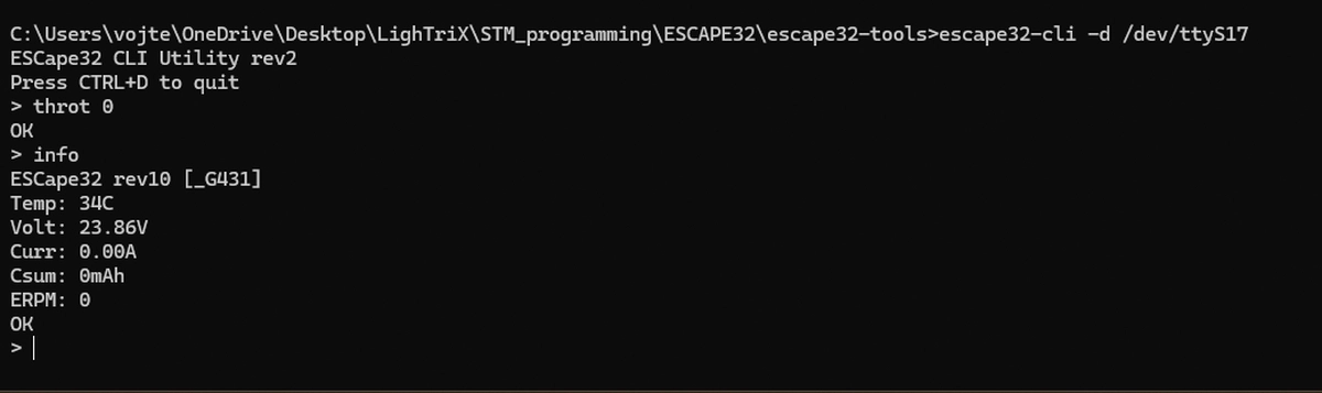
Once flashed, the ESC can be configured from the radio over CRSF (see Radio Configuration), over a Wi-Fi Link board, or over the serial CLI.
Disconnect power before changing any wiring.
Bootloader flashing
The bootloader normally needs to be installed only once. Current ESCape32
update tools require revision 4 with bootloader write protection enabled. If
BOOT4_PA2-rev4 is already installed and protected, continue at
Firmware flashing. If its state is unknown, reinstall it
over SWD before updating the firmware.
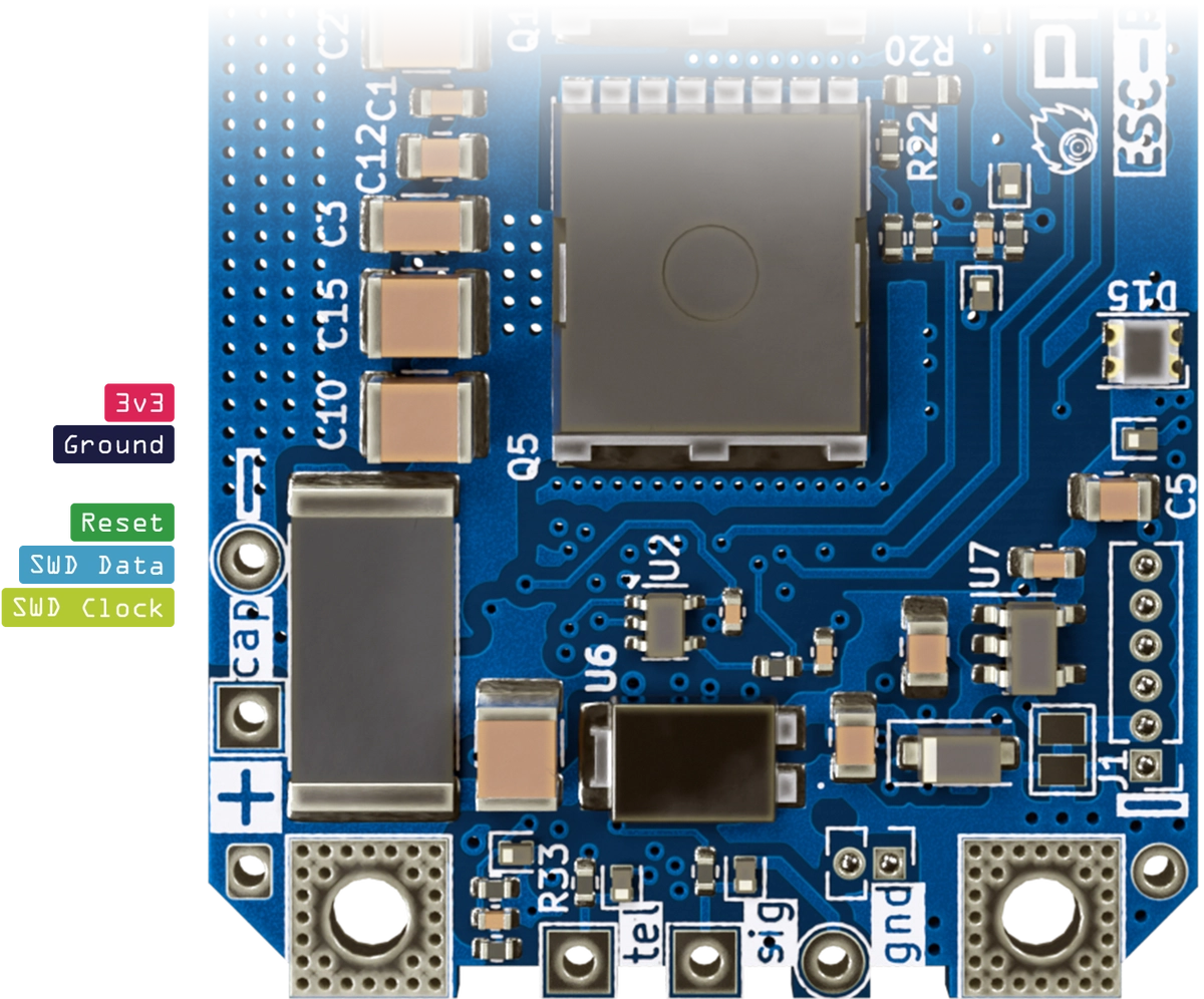
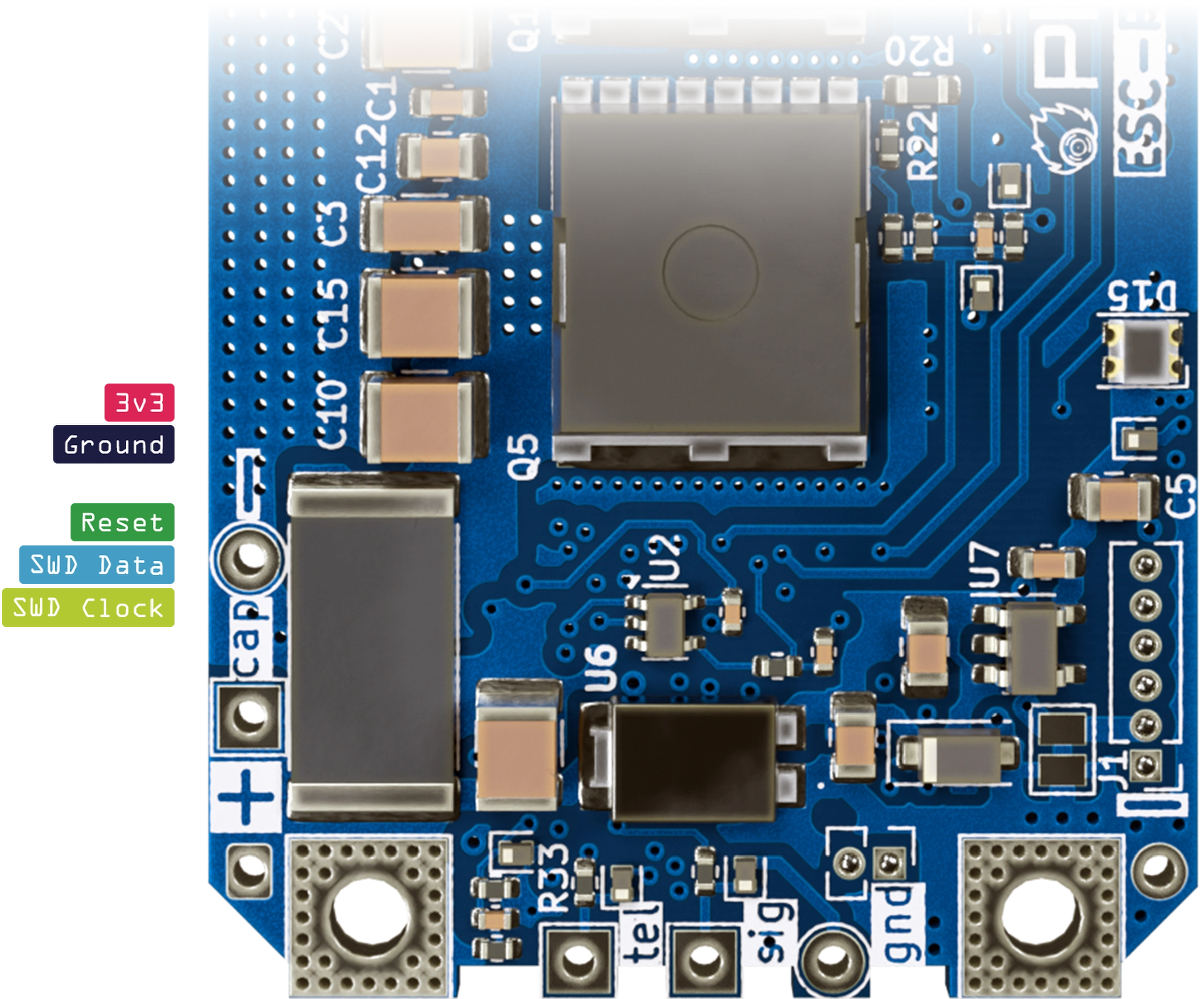
Connect the ST-Link V2 programmer to the ESC’s SWD connector.
- 3.3 V to 3
- GND to G
- RST to R
- SWDIO to D
- SWCLK to C
The connector has ESD protection, but it is not protected against incorrect wiring. Check every pin before connecting USB power.
Connect the ST-Link V2 programmer to your computer.
Start STM32CubeProgrammer and select the ST-Link V2 by its serial number.
Click
Connectand wait for the connection to be established.Select
Full chip eraseto erase the ESC’s flash memory. This also removes the installed firmware and saved configuration.Open
Erasing & Programmingand select the bootloader binary.The bootloader is distributed as a
.binfile, so set the Start address to0x08000000.Click
Start programmingand wait for the process to finish.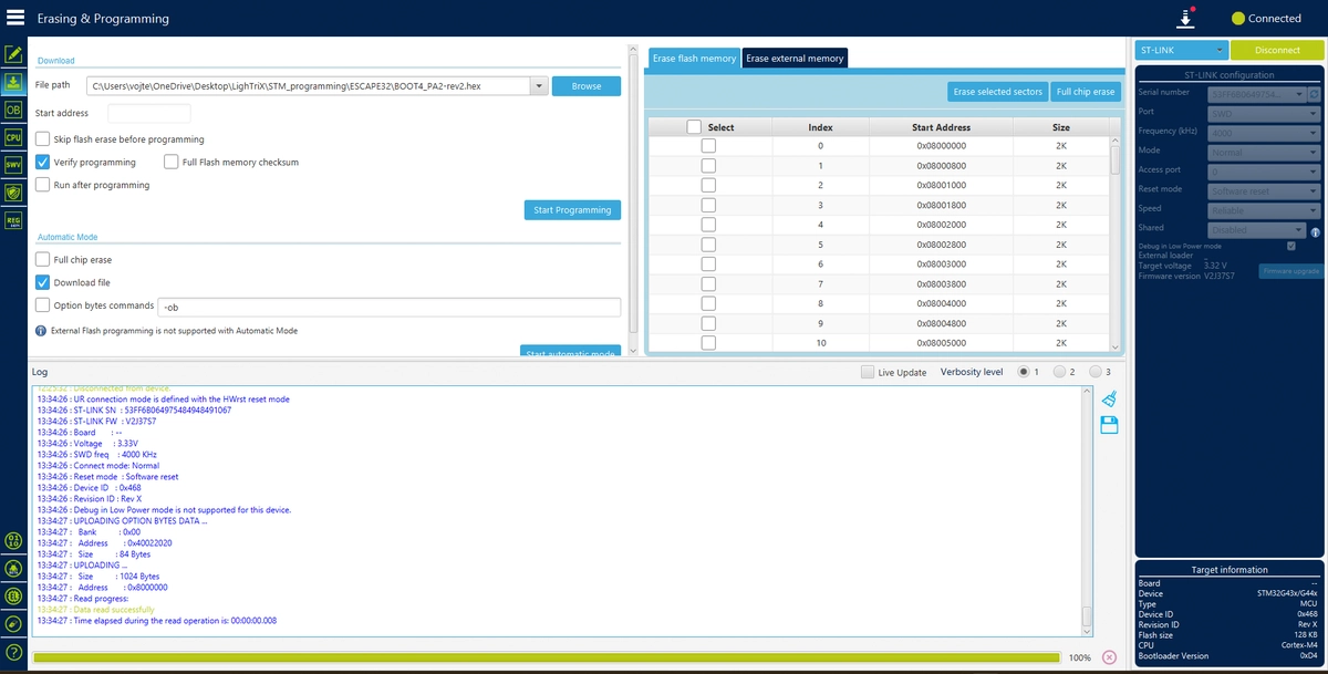
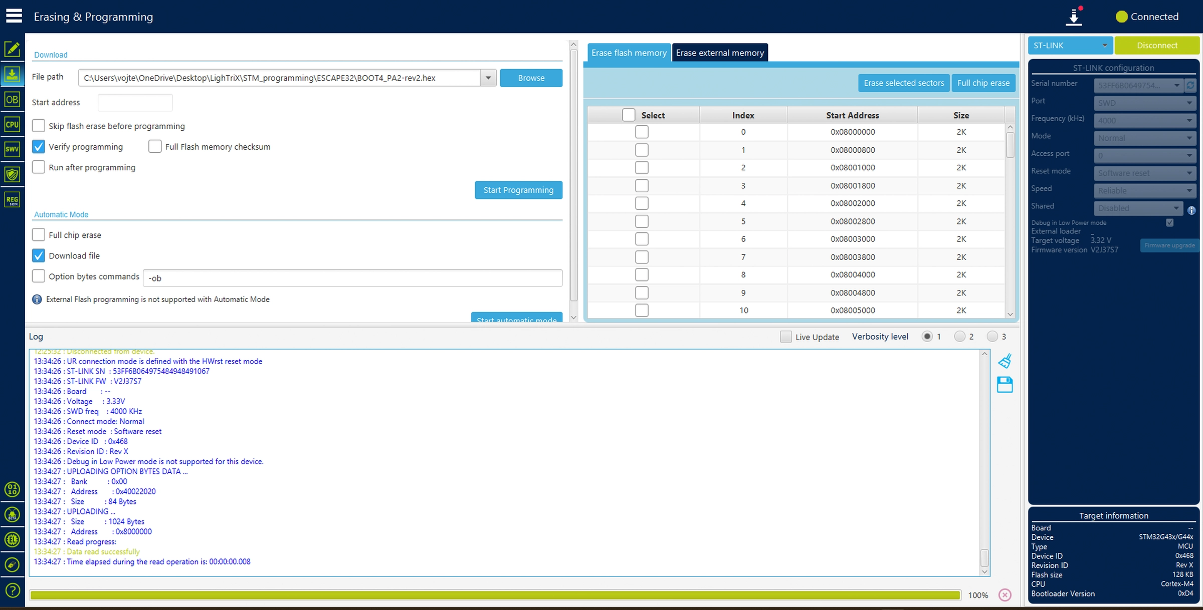
Open
Option bytes, setBOOT_LOCKunder Secure Protection, and clickApply.
Once the bootloader is flashed, disconnect the programmer before changing the wiring for the firmware update.
After recovery, continue with Firmware flashing.
Need help with your setup? Contact us.