Quick Start Guide
Required hardware
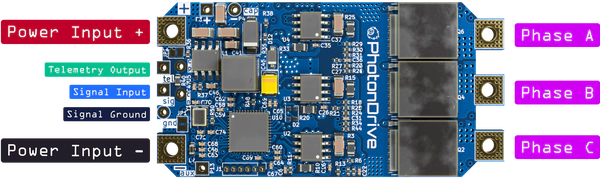
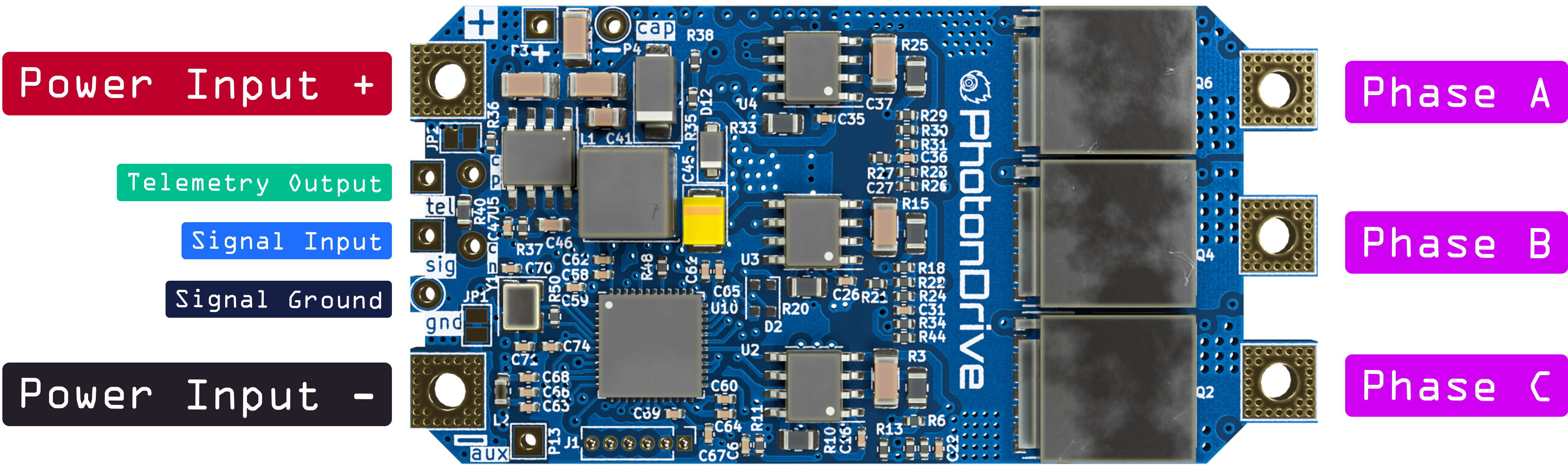
- PhotonDrive ESC-R-150 or ESC-A-150
- PhotonDrive PDB 500 HotSwap
- Flight controller
- BLDC motor
- Battery or other power source (6S-15S LiPo recommended)
- Power leads (8-12 AWG cable recommended)
- Signal wire
We strongly recommend using high-quality silicone-insulated wire for all power connections.
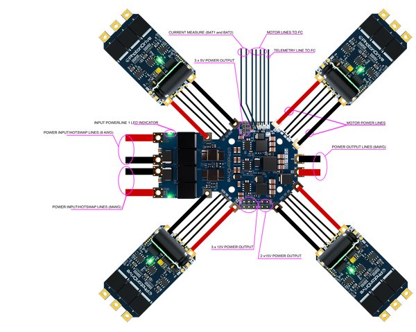
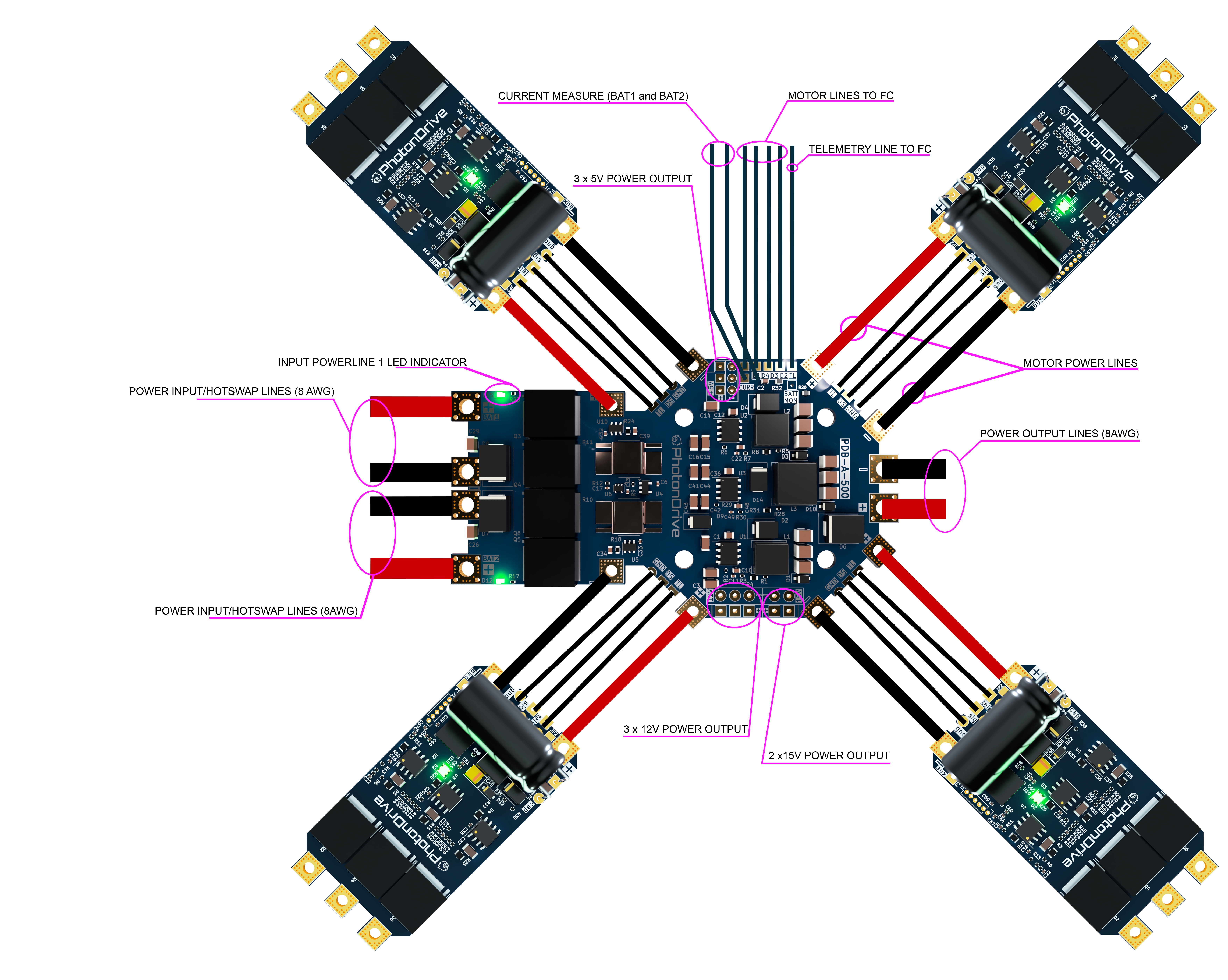
Wiring diagram
Make sure your setup matches the wiring diagram below. The ESC-R-150 and ESC-A-150 are designed to be used with the PhotonDrive PDB 500 HotSwap, however other power distribution boards are supported as well.
First power-up
Before powering up the circuit, check for shorts between the power leads. First power-up should be done at low voltage (15V) to test the setup while minimizing potential damage.
A “smoke stopper” module is highly recommended before first power-up.
Connect a low voltage power source to the PDB and power up the system. The ESC should initialize and the motor should beep to indicate that it’s ready for operation.
Configuration
Each ESC can be configured separately through the flight controller (e.g. using Betaflight).
The ESC configuration depends on the firmware used. The following links refer to the ESCape32 wiki. For AM32 check out their wiki page.
For low level configuration, check out the configuration wiki. For on-the-fly configuration, you may use the DShot programming protocol.
Flashing custom firmware
Flashing custom firmware is only recommended for advanced users. A flashing failure may result in a bricked board or even hardware damage.
The ESC-A-150 supports custom firmware flashing via SWD. For a complete guide click here.