Flashing Guide
Flashing custom firmware is only recommended for advanced users. A flashing failure may result in a bricked board or even hardware damage.
Required hardware
- PhotonDrive ESC-A-150
- ST-Link V2 programmer dongle
- Flight controller
- BLDC motor
- Battery or other power source (6S-15S LiPo recommended)
- Power leads (8-12 AWG cable recommended)
- Signal wire
We strongly recommend using high-quality silicone-insulated wire for all power connections.
Required software
Binaries for the pre-installed firmware can be found below:
Download original ESCape32 bootloader Download original ESCape32 firmwareBootloader flashing
This guide uses the ESCape32 firmware as an example. We recommend searching for guides specific to your firmware on the internet.
Before flashing the custom firmware, its bootloader must be installed onto the ESC over SWD. The bootloader is a small program that allows the ESC to be flashed using the input signal pin.
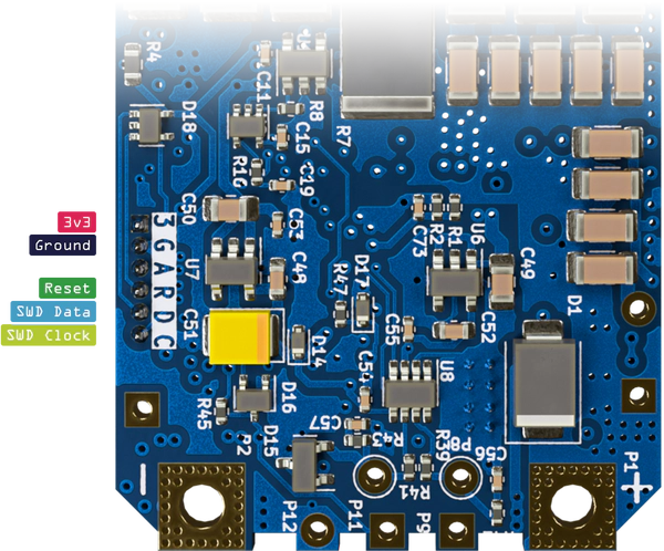
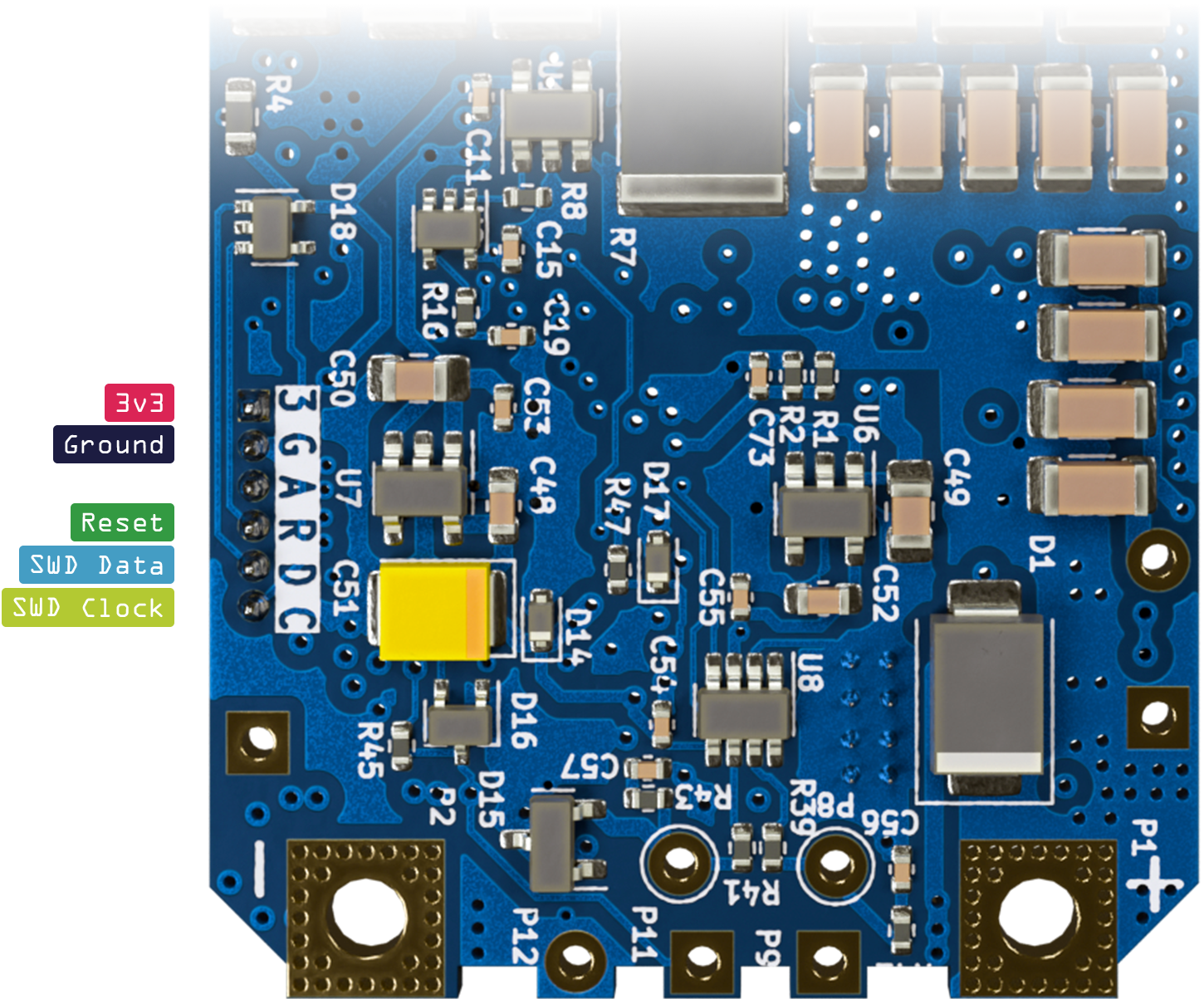
Connect the ST-Link V2 programmer to the ESC’s SWD connector.
- 3.3V to 3
- GND to G
- RST to R
- SWDIO to D
- SWCLK to C
Though the flashing connector pins have ESD protection, be careful when attaching the programmer not to cause damage.
Connect the ST-Link V2 programmer to your computer.
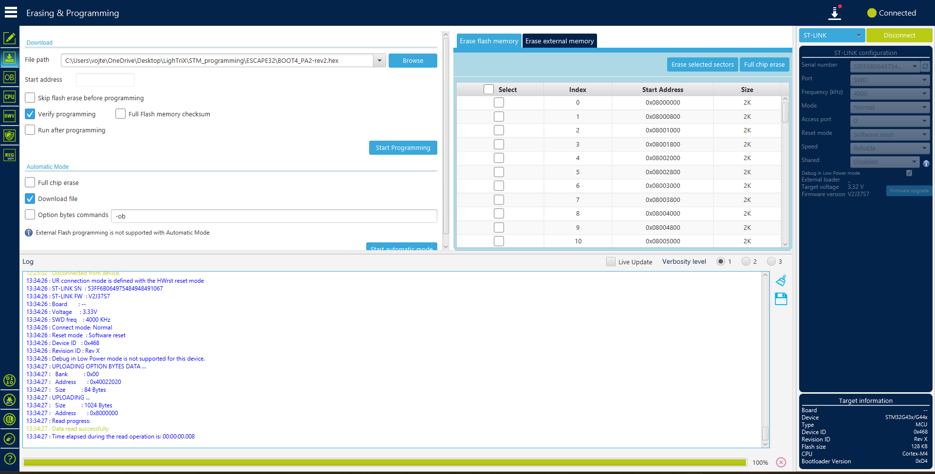
Start the STM32CubeProgrammer and select your ST-Link V2 programmer in the right sidebar using the Serial number field.
Click
Connectand wait for the connection to be established.In the right sidebar, click
Full chip erase(2nd to last option) to erase the ESC’s ROM.Next, click on
Erasing & Programming(2nd option) and select the bootloader binary (preferably.hexfile).If the bootloader only comes as a
.binfile, set the Start address to0x08000000.Click
Start programmingand wait for the process to finish.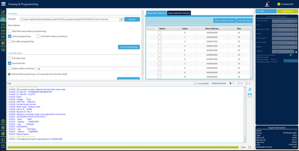
Lastly, click
Option bytes(3rd option) and make sure theBOOT_LOCKbit (under Secure Protection) is set, then clickApply.
Once the bootloader is flashed, unplug the ST-Link V2 programmer and proceed with flashing the firmware itself.
Firmware flashing
This section heavily relies on the firmware you are using. Please refer to the firmware’s documentation for specific instructions.
For ESCape32, you will need the ESCape32 Tools.
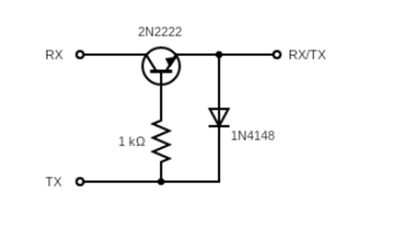
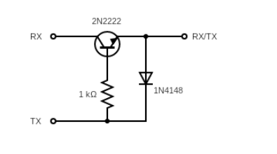
Connect a generic USB-Serial adapter to the ESC’s input signal pin via a diode-transistor circuit.
- RX to Collector
- TX to Base via a 1kΩ resistor
- Emitter to ESC Input Signal
- Emitter to TX via a diode
- GND to ESC GND
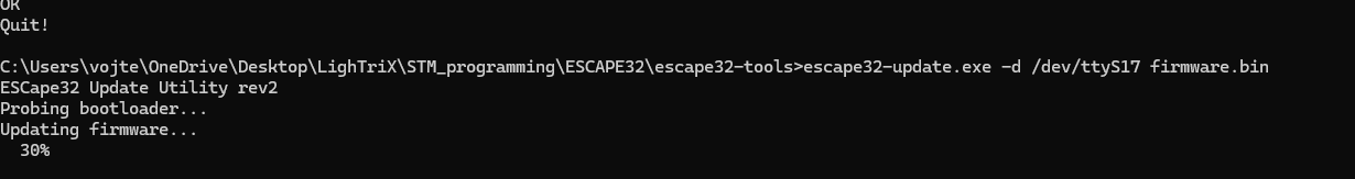
Flash the ESCape32 firmware using the ESCape32 Tools.
./escape32-update -p <serial-port> <path-to-firmware-file>On Windows, use serial port format
/dev/ttyS#where#is the COM port number minus one (e.g.,COM4→/dev/ttyS3).For more information, check out the ESCape32 installation guide.

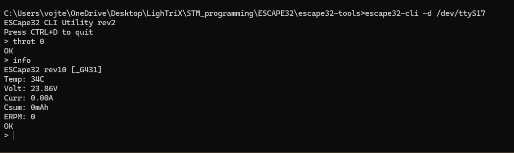
Test the ESC with the ESCape32 CLI tool.
./escape32-cli -p <serial-port>Start by typing
throt 0to arm the ESC, then usethrot <value>to set the throttle (0-2000).Be extremely cautious when operating the ESC. Make sure the motor is well mounted and won’t move before setting the throttle.
Do not run the motor at high power or for extended periods of time without a propeller, the ESC may overheat.

And just like that, you’re done!
Happy flying!